

Lead Provider of Environmental Test Chamber


 Posted on
17 04 2026
Posted on
17 04 2026


 Temperature cycling testing is a very important process. It makes sure electronic components and systems stay reliable and strong over time. These items must work well in places where temperatures change often. The tests copy real-life conditions. In real life, components face quick shifts in temperature. This process helps find possible weak points early. It stops them from causing big harm when the product is in actual use.
This article looks at five common types of problems. Temperature cycling tests show these problems a lot. We will talk about the main reasons for these failures. We will also suggest some practical ways to reduce them. In addition, we give a quick look at how to choose the right test chamber for your needs. We introduce LIB’s temperature cycling solutions too.
Temperature cycling testing puts a component or product through many temperature changes. These changes usually range from high to low. The test controls the speed of the changes. It also controls the time the product stays at each temperature. Plus, it has a set number of cycles. This kind of testing tries to copy extreme conditions in the environment. Products may meet these conditions during their full life cycle.
The key parts of these tests include several things.
Temperature Range: This is the high and low temperatures that the product faces in the test.
Ramp Rate: This is the speed at which the temperature moves between the high and low points.
Dwell Time: This is the length of time the product stays at each extreme temperature.
Cycle Count: This is the total number of cycles the product goes through in the test.
These tests can spot hidden weaknesses. The weaknesses may be in the product’s design. They could also be in the choice of materials. Or they might be in how the parts are put together. The test can show possible failures. Some examples are solder joint cracking, PCB delamination, and seal failures. It is important to understand these failure types. We also need to know their root causes. This knowledge helps improve the overall quality and reliability of electronic components.
 This is the first common issue that shows up often in tests. Let us look at how it appears and what causes it.
Solder joints often show wear first in these tests. This is especially true for those in BGA packages. Common signs include a few things.
Intermittent failure: The product may work on and off. It might fail after a long time of use.
Increased resistance: Solder joints may show higher electrical resistance. This affects how well the product performs.
Micro-cracks: Fine cracks may form in the solder joints. These appear in areas that go through repeated thermal expansion and contraction.
Different materials in the device expand and contract at different rates. This happens when temperatures change. The PCB and the solder are good examples. This difference creates mechanical stress at the solder joints. Over time, the stress can cause cracks or fatigue.
The repeated thermal cycling makes the solder material break down. It loses its mechanical strength as well.
You can choose solder alloys that resist fatigue better. They should also have good thermal properties.
Redesign the solder joint for improvement. Think about better PCB designs. You could optimize pad shapes. Or use underfill materials. These reduce stress at the solder joints.
Try to lower the CTE mismatch. Make the device design so that the coefficient of thermal expansion of different parts matches better.
Next we look at another frequent problem that affects the board itself. This part shows what happens when layers start to come apart.
PCB delamination happens when the layers of the PCB come apart. Thermal stresses cause this. It shows up in several ways.
Layer separation: The separate layers of the PCB pull away from each other.
Bubbling or warping: The delamination can cause visible changes in shape. This might affect the device’s function.
Loss of conductivity: The layer separation can break electrical paths. This leads to failures.
The bond between the copper layers and the PCB material may not be strong enough. It cannot handle the thermal stresses from temperature cycling.
Moisture can get inside the PCB sometimes. When temperatures change, the moisture turns to vapor. This creates internal pressure. The pressure then causes delamination.
Extreme temperature changes can also cause problems. Rapid or very big shifts put stress on the material. The stress goes beyond what the material can take.
Pick high-quality materials for the PCBs. Choose ones with high glass transition temperatures. They should have low moisture absorption too.
Improve the way you make the PCB. Use high-quality bonding materials and methods in the manufacturing process.
Design the PCB to relieve stress better. Use improved stacking methods. Adjust copper thickness. These steps help deal with thermal expansion issues.
Warpage is a common issue that appears in bigger parts during tests. Here we explain why it occurs and how to stop it.
Warpage and deformation often appear in temperature cycling tests. This is more common in bigger devices or packages. Signs include these points.
Bending or twisting: The PCB or component may bend or twist. This causes misalignment.
Solder joint stress: Warpage adds extra stress to solder joints. It can lead to fatigue and cracking.
Assembly issues: Misalignment creates problems during assembly. It makes connecting components hard. It can also make fitting the device into enclosures difficult.
The coefficient of thermal expansion does not match between different materials. Solder, PCB, and components are examples. This mismatch causes deformation when temperatures cycle.
Larger components or designs that are not balanced suffer more. They warp easily under temperature stress.
Select materials that work well in high-temperature settings. Or choose materials with CTE values that match better.
Arrange the components on the PCB carefully. Use layouts that are symmetric. This minimizes stress from temperature changes.
Add more mechanical support. Use fixtures in the design. Or improve the assembly to hold components steady. This prevents bending.
Seals protect sensitive parts, but they can fail under repeated temperature changes. This section covers the signs and simple fixes.
Seal failure happens in parts that need hermetically sealed enclosures. Sensors and precision electronics are examples. Symptoms show in these ways.
Aging seals: The seals that protect inside parts may become brittle. They lose their strength over time.
Leakage: Leaks can develop in the enclosure. Moisture, air, or contaminants can then get in.
Performance degradation: The seal failure can lower the device’s performance. Sensors may lose sensitivity. Electronics can fail too.
Temperature changes happen over and over. This makes seals expand and contract repeatedly. The material gets tired as a result.
Sometimes the seal materials are not right. They may not hold up well to the thermal cycling process.
The sealing design might have issues. It may not give enough compression. Or it may not keep pressure well enough.
Choose better materials for seals. Pick elastomers that have high thermal stability. They are made for thermal cycling.
Redesign the sealing mechanism. Make sure it has better compression. Create stronger bonds too.
Do thorough leak testing. This finds any weak spots. Do it before full production starts.
Electrical problems often appear as small, hard-to-find issues during testing. Let us review why they happen and how to prevent them.
Electrical failure during temperature cycling tests is often not constant. The device works sometimes but not always. Symptoms include these.
Voltage or resistance drift: Electrical parameters may change slowly. This causes wrong readings or lower performance.
Intermittent connections: Some parts may lose contact for short times. This leads to function problems.
Connections can be poor or weakly designed. They may open or close at random times under thermal stress.
Small cracks can form in solder joints or components. These cause temporary contact issues.
Some components like sensors or resistors change over time. Their characteristics drift because of temperature shifts.
Use strong connectors and terminals. Make sure they are rated for the temperature range in use.
Prevent micro-cracks in the design. Avoid flaws that cause them. Poor solder joints or lack of stress relief are examples.
Monitor electrical parameters on a regular basis. This helps catch issues early. It prevents long-term damage.
After going through these common failures, it is helpful to consider tools that make testing easier and more effective.
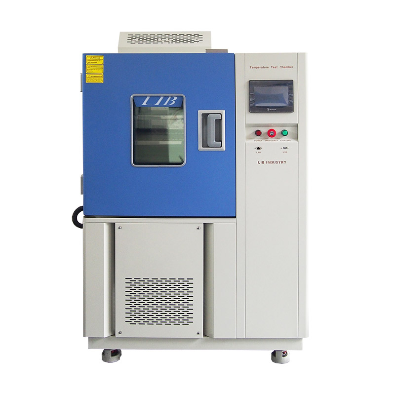
LIB’s temperature cycling test chambers provide great reliability and flexibility. They work well for many different industries. The chambers are built to meet tough testing needs for products. They give high accuracy and repeatable results. The designs include advanced features. These support both standard tests and ones with fast change rates. They allow exact copying of real-world conditions.
LIB’s chambers have several strong parameter.
| Feature | Advantage |
|---|---|
| Temperature Range | -20℃ ~+150 ℃ |
| Low type | A: -40℃ B:-70℃ C -86℃ |
| Temperature fluctuations | ± 0.5 ℃ |
| Temperature deviation | ± 2.0 ℃ |
| Heating rate | 3 ℃ / min |
| Cooling rate | 1 ℃ / min |
| Controller | Programmable color LCD touch screen controller, Multi-language interface, Ethernet , USB |
| Safety device | Over-temperature protection; over-current protection; Refrigerant high-pressure protection; Earth leakage protection |
| Environmental conditional | 5℃~+40 ℃ ≤85% RH |
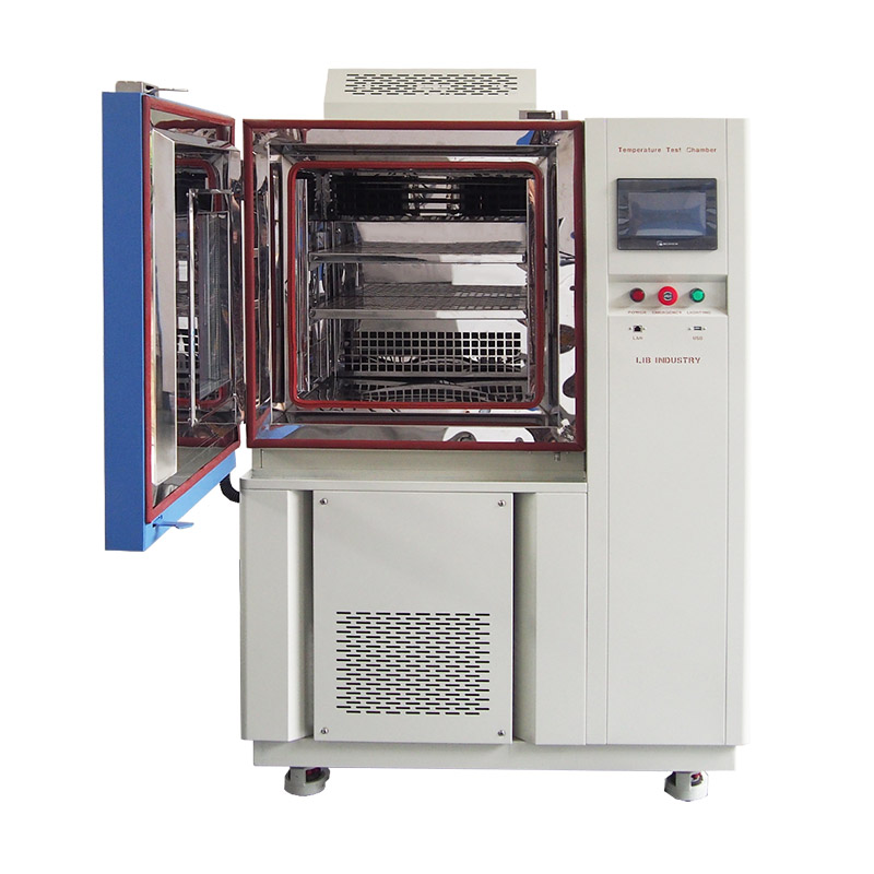
These chambers work for small parts or big assemblies. They give excellent performance. This allows full reliability testing. Your products will be ready for the hardest environmental challenges.
LIB Environmental Simulation Industry is a top supplier of environmental test chambers. The company focuses on products for temperature, humidity, and vibration testing. It has many years of experience in the field. LIB offers modern solutions. These help manufacturers check product reliability. The solutions cover industries like electronics, automotive, and aerospace. LIB works hard to give custom solutions. They meet the exact needs of each customer.
Temperature cycling testing plays a key role. It finds possible failure types. This improves the reliability of electronic components. When manufacturers understand common failure reasons, they can create stronger products. These products handle tough temperature environments better. LIB’s temperature cycling test chambers offer a reliable and efficient method. They let businesses do these tests well. This helps raise the quality of their products.
Temperature cycling subjects a product to repeated temperature changes. Thermal shock tests expose the product to a sudden temperature change instead.
It spots possible weak spots. Examples include solder joint cracking or PCB delamination. Manufacturers can then improve the design. They do this before they start production.
Solder joint cracking, PCB delamination, warpage, seal failure, and intermittent electrical failure are common issues.
Think about several factors. These include temperature range, ramp rate, chamber size, and data logging abilities. Use them when you choose a test chamber.
Yes, it can. Temperature cycling testing copies the extreme temperature changes. Products may face these changes in real applications.


 EN
EN


