

Lead Provider of Environmental Test Chamber
 Introduction Regulatory compliance holds an important place in making sure medical devices meet worldwide safety, quality, and performance standards before they enter the market. In medical device testing, especially stability testing, compliance makes certain that environmental factors like temperature and humidity do not harm device strength or operation. Walk-in stability chambers have become key tools for these compliance tasks. They supply controlled and repeatable test settings.
Medical device testing takes place in a detailed international regulatory setting. Main regulatory bodies include the U.S. Food and Drug Administration (FDA), the European Medicines Agency (EMA), and groups such as the International Organization for Standardization (ISO). Each body applies specific rules that guide product design, production, and testing. Standards like ISO 13485 set needs for quality management systems in medical device production. At the same time, ICH Q1A(R2) offers advice on stability testing methods to keep product steadiness over time. Matching stability testing to these needs is not just a routine task. It is vital for market approval and patient safety. Compliance ensures that each environmental test truly shows real-world conditions during a device’s full life cycle.
Temperature and humidity rank as two major factors that influence material lasting power, adhesive work, and electronic trustworthiness in medical devices. Changes in these factors can cause breakdown or failure. This happens mostly in parts based on polymers or electronics. Stability chambers copy these environmental pressures to evaluate long-term product work in controlled settings. Walk-in stability chambers offer even environmental control over large areas. This allows testing of several units or setups at the same time. They keep steady temperature and humidity levels. Therefore, they provide results that can be repeated. These results support both design strength and shelf-life claims. The connection between environmental control and life cycle reliability builds trust in product quality during regulatory reviews.

To move into how walk-in stability chambers aid regulatory following, we need to examine their basic design features and work functions. These elements link directly to compliance structures.
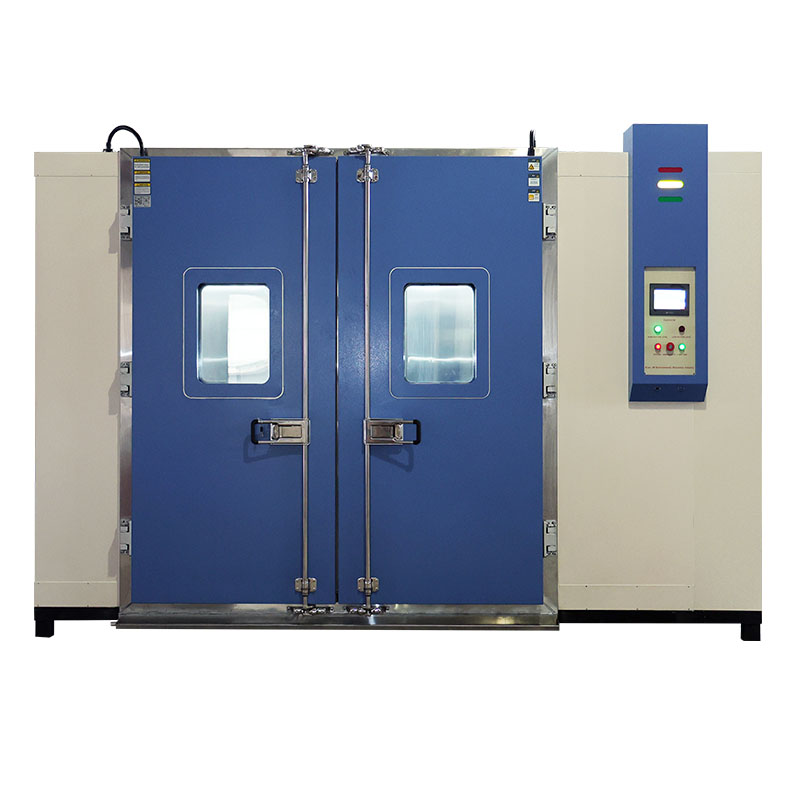
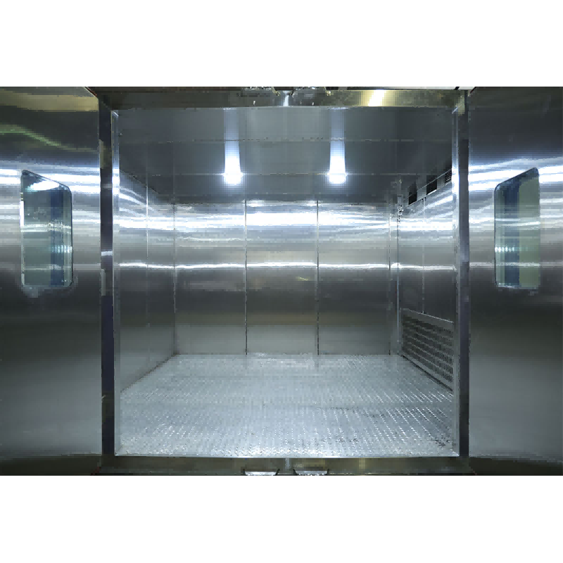
Walk-in stability chambers are designed to hold exact environmental conditions for long periods. Their build usually features insulated panels that can be assembled, stainless-steel insides to resist rust, and strong floors that can bear heavy weights. Control systems adjust temperature using PID-managed heating and cooling parts. They also control humidity with steam producers or dryers. Fans for air movement ensure even spread in the chamber area. This removes warm or cool spots. Such evenness is a key element in validation studies. Linking with monitoring software adds to tracking ability. It supports constant data recording, alert signals, and audit path creation that meets Good Laboratory Practice (GLP) standards.
To fulfill Good Manufacturing Practice (GMP) needs, walk-in chambers go through full validation processes. These confirm their power to maintain set conditions within given limits. Calibration steps check sensor correctness using traceable reference tools. This guarantees repeatability across test runs. Record-keeping practices cover calibration papers, validation reports, and error logs. These form part of the compliance proof checked during inspections by regulatory bodies.
Before use in controlled settings, walk-in stability chambers must complete qualification steps. These verify their setup soundness and performance steadiness.
Qualification includes three main stages:
Periodic requalification ensures continued compliance over time by detecting drift or degradation in system components.
Compliance with 21 CFR Part 11 requires safe electronic data management systems. These feature user authentication, audit trails, and tamper-proof records. Automated alarms warn operators of changes beyond tolerance limits. Meanwhile, built-in reporting tools simplify paperwork during audits. Secure archiving ensures traceability of all test data throughout retention periods defined by regulatory requirements.
As part of a solid quality assurance plan, risk management spots possible sources of non-compliance. These could threaten test validity.
Common risks include equipment breakdown from part wear, calibration shift leading to wrong readings, or sudden changes from power stops. Such shifts can make whole study data sets invalid if not found quickly.
Preventive maintenance plans reduce operational breakdowns. They do this through regular checks of sensors, compressors, humidifiers, and control units. Corrective Action/Preventive Action (CAPA) structures matched to ISO 14971 principles aid organized replies when issues happen. Constant monitoring of chamber performance patterns allows early action before shifts affect results.
 To link risk management results with company oversight tools, fitting into a strong QMS is essential.
Stability testing must fit within the larger QMS under FDA’s Quality System Regulation (21 CFR Part 820). Documentation control provides traceability from first chamber qualification through ongoing performance checks. Internal audits regularly examine following QSR standards. This keeps lasting compliance readiness at all work levels.
Automation lowers human mistakes. It also improves process openness through digital screens that show live environmental details. Fitting with Laboratory Information Management Systems (LIMS) allows central data reach. This supports work across multiple sites during global clinical trials or production tasks. Predictive analysis further improves chamber use. It does so by predicting maintenance needs from past performance trends.
As technology grows quickly in regulated fields, new standards are changing views on environmental simulation tools like walk-in chambers.
Coming changes to ISO guidelines stress better traceability through digital validation records. They also add advanced sensor tech that can self-check using IoT connection setups. Artificial intelligence-based analysis will allow predictive modeling of chamber actions under changing load types. This will improve both efficiency and reliability around the world.
Keeping long-term compliance needs more than rule following. It requires team dedication across all groups in product development stages. Regular training programs give staff fresh regulatory knowledge. At the same time, teamwork between QA groups ensures match between R&D ideas and compliance duties.
Xi’an LIB Environmental Simulation Industry provides modern walk-in stability chambers. These are built especially for pharmaceutical and medical device uses that need tight environmental control accuracy.
|
Feature |
Specification |
Benefit |
|
Temperature Range |
-20°C to +60°C |
Suitable for accelerated aging & long-term studies |
|
Humidity Range |
20%–95% RH |
Enables diverse climatic simulations |
|
Uniformity |
±1°C / ±3% RH |
Ensures consistent exposure across samples |
|
Control System |
PLC + Touchscreen Interface |
Provides intuitive operation & remote monitoring |
|
Data Logging |
USB/Ethernet connectivity |
Facilitates audit-ready documentation |
|
Safety Features |
Over-temperature protection & alarms |
Ensures reliable operation |
Additional advantages include modular build that allows flexible setup plans in lab areas. Plus, energy-saving cooling systems cut running costs without losing accuracy.
Xi’an LIB Environmental Simulation Industry has set itself as a dependable supplier. It delivers certified walk-in stability chambers that meet GMP-compliant design standards worldwide. Their answers fit smoothly into current QMS structures. They support clients through each stage—from installation qualification to regular calibration services. This ensures steady compliance readiness during product life cycles.
Regulatory compliance stays at the core of medical device testing. Here, exact environmental simulation sets product reliability marks required by global bodies like FDA or EMA. Walk-in stability chambers act as vital resources. They help makers not only meet but surpass these needs. Validated control abilities ensure steady test results that line up with changing international standards.
They provide controlled environments necessary for validating product durability under varying temperature/humidity conditions ensuring compliance with ISO 13485 requirements.
Requalification is recommended annually or following any major maintenance activity impacting system performance according to GMP guidelines.
Essential documents include IQ/OQ/PQ reports, calibration certificates, deviation logs, maintenance records, and electronically archived monitoring data compliant with 21 CFR Part 11 regulations.
View more product


 EN
EN


