

Lead Provider of Environmental Test Chamber


 Posted on
22 01 2026
Posted on
22 01 2026


PV module reliability testing is not just a checkbox for certification. It is a way to catch performance loss, safety risks, and warranty drivers before production ramps. The most searched questions from PV manufacturers and third-party labs are practical ones: what are the exact conditions, how long does each test take, what should be measured during and after exposure, and how to read common failures like PID, moisture ingress, and solder fatigue.
This article turns standard-style language into an execution workflow. It also translates requirements into an equipment capability checklist, because most delays in PV reliability programs come from gaps in stability, sample mounting, logging, and repeatability.
PV modules fail in slow, coupled ways. Heat moves materials. Moisture moves ions. Repeated cycles grow micro-cracks and stress interfaces. A single test rarely tells the whole story. A process view does, because it forces decisions on sequencing, stabilization time, measurement points, and what “pass” means for both safety and power.
A short transition helps here. Once the purpose is clear, the next step is understanding what each test is trying to accelerate.
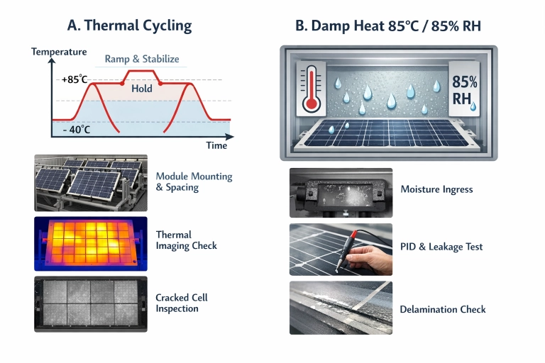
Thermal cycling is used to stress solder joints, interconnect ribbons, cell cracks, and interfaces that move at different rates with temperature. Damp heat 85°C/85%RH for 1000 hours is used to accelerate moisture-driven degradation, insulation weakness, corrosion, and ion migration effects that can show up as PID or leakage. Humidity freeze targets moisture ingress and delamination risks by pushing trapped water through phase change and contraction stress.
Thermal cycling is often treated as “run the profile and wait.” In practice, results depend on ramp behavior, dwell stability, and how the module is mounted.
A short transition is useful. Start with what the lab must lock down, then move to what should be measured.
Thermal cycling needs stable control at the module plane, not only at the chamber sensor. Large modules can lag behind air temperature during ramps and dwells. For a lab workflow, the critical items are stabilization time at the high and low plateaus, air circulation that keeps uniformity across the module face, and a mounting method that does not introduce extra bending or constraint.
Measurement planning should match the failure physics. Many labs pair thermal cycling with pre- and post-exposure electrical checks and imaging, because mechanical fatigue can show up as subtle power loss first and visible cracks later.
Interconnect fatigue often shows as increased series resistance and localized loss patterns on imaging. Cell cracks can create stepwise drops, especially after additional handling. Junction box or lead failures can show up as intermittent faults during functional checks. When thermal cycling is done well, it reveals where the module is mechanically fragile, not just whether it survives.
Damp heat 85°C/85%RH for 1000 hours is one of the most searched terms in PV reliability because it is long, expensive, and often blamed for schedule slips. The core technical challenge is not reaching 85/85. It is holding it steadily for weeks while maintaining uniformity, logging, and safe water management.
A short transition matters here. The biggest mistake is treating damp heat as “set and forget,” then discovering data gaps or drift at hour 600.
Long runs expose weak points in humidity generation, drainage, sensor drift, and chamber sealing. The practical expectation for a depicting damp heat program includes stable temperature and humidity control, recovery after door openings, and alarms that prevent silent excursions overnight. A lab also needs consistent sample spacing and airflow to avoid edge effects where modules near air inlets see different moisture loading than modules elsewhere.
Common outcomes include insulation resistance reduction, corrosion at connectors, and encapsulation-related issues such as delamination or haze changes. PID is frequently discussed in the damp heat context because moisture and elevated temperature can make leakage pathways easier. If the lab is tracking PID risk, it is common to include electrical leakage checks and insulation measurements in the workflow, not only power checks at the end.
Moisture ingress can also show up indirectly. Discoloration, backsheet changes, or junction box seal issues may appear before major electrical loss. The important point is to align the measurement set with the suspected degradation path, otherwise the test produces a “pass/fail” label without insight.
Humidity freeze is typically used to stress the module’s ability to cope with moisture entry and freezing. Trapped water expands when frozen and can force open interfaces that were marginal but stable at room temperature. It also drives contraction mismatch between layers.
A short transition helps: humidity freeze is not just “cold.” It is “cold plus water in the wrong place.”
Delamination and seal failures often become more visible after humidity freeze. Edge seal weakness can show up as local bubbling or loss of adhesion. If moisture has entered the laminate stack, the freeze step can make small defects grow. For labs, a practical reading approach combines visual inspection with electrical checks, because some interface problems start as localized defects and only later become measurable power loss.
A reliability workflow is only as good as the equipment’s ability to run it repeatedly. This is where many PV labs struggle when scaling from a few modules to daily throughput. The checklist below translates “standard wording” into capabilities that affect cycle time, data quality, and confidence.
A short transition is useful here. Instead of arguing about numbers in isolation, connect each capability to the risk it controls.
| Capability item | Why it matters in PV reliability runs | What to define in a lab plan |
|---|---|---|
| Temperature and humidity stability over weeks | Damp heat 85/85 runs can drift, and small excursions can undermine confidence | Control tolerances, calibration interval, alarm rules, and data sampling rate |
| Uniformity across large module surfaces | Edge-to-center differences change moisture loading and fatigue behavior | Sensor placement, load maps, module spacing, airflow constraints |
| Ramp behavior and dwell stabilization time | Thermal cycling results depend on what the module experiences, not just air setpoint | Ramp limits, dwell duration at module plane, stabilization criteria |
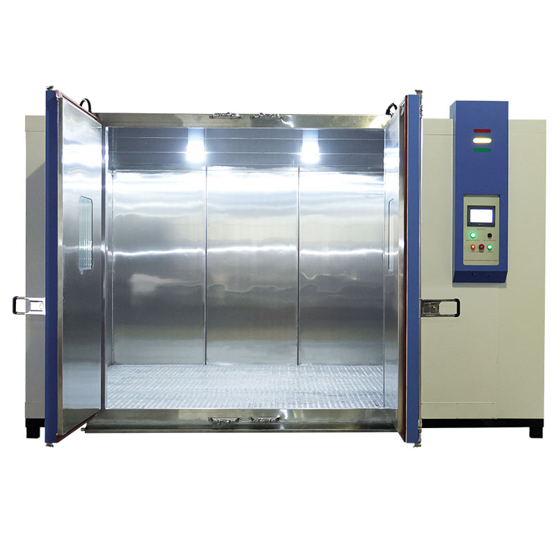
| Large-chamber volume and loading strategy | Throughput depends on how many modules run per batch without blocking airflow | Maximum load rules, rack design, spacing rules, door-open recovery plan |
| Data logging and traceability | Certification audits and internal failure analysis need continuous records | Log format, time sync, event flags, backup method, excursion reporting |
Labs often run these tests as a sequence because each stresses a different risk, and the order can help isolate mechanisms. Thermal cycling can expose mechanical weak points early. Damp heat can then reveal moisture-driven degradation on a module that is already mechanically stressed. Humidity freeze can be used as a targeted test for sealing and interface weakness, especially for designs with higher moisture ingress risk.
The key is to plan measurement gates. A basic workflow approach is to define pre-test baseline checks, interim checks at scheduled milestones for long damp heat runs, and post-test checks with a consistent method so results can be compared across batches.
PV teams search for “common failures” because root cause work is expensive. A structured reading approach reduces false conclusions.
PID is often discussed as a system-level outcome of leakage pathways and ion migration. It tends to correlate with insulation weakness, moisture exposure, and electrical stress conditions used in PID-focused tests. In a damp heat context, PID risk signals can include insulation resistance changes and performance loss patterns that are not uniform.
Encapsulation moisture ingress and delamination often show up as visible interface changes before large power loss. When the test includes humidity freeze, defects can become more obvious because freeze expansion forces open marginal bonds.
Solder ribbon fatigue and interconnect issues are commonly tied to thermal cycling because repeated expansion mismatch drives fatigue. These faults often appear as localized electrical loss or increased series resistance rather than immediate catastrophic failure.
The practical point is to match the suspected failure to a measurement that can confirm it, instead of relying only on end-of-test power values.
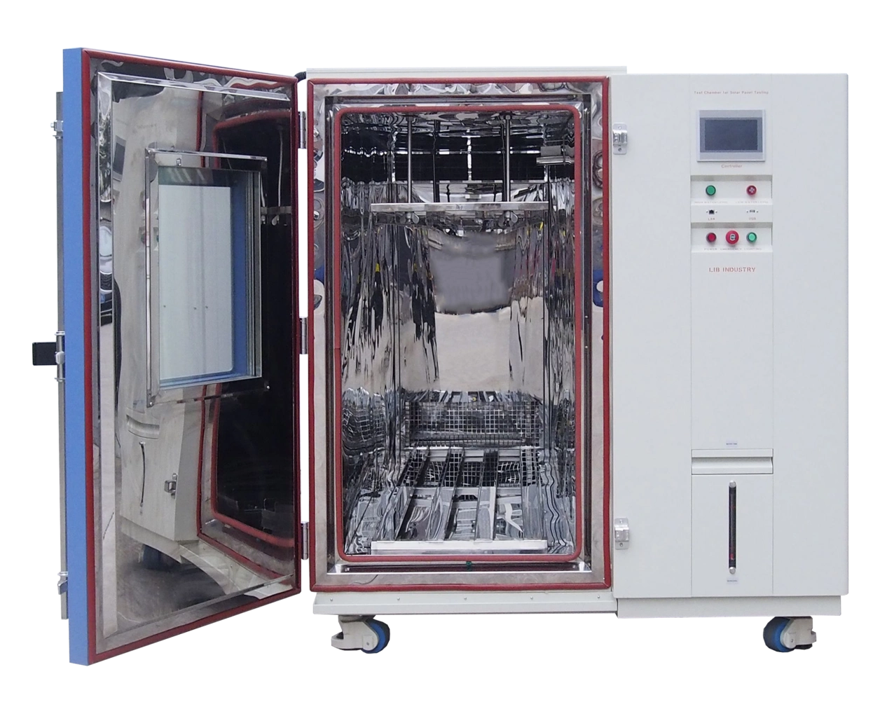
Xi’an LIB Environmental Simulation Industry presents itself as an environmental simulation equipment supplier covering design, manufacturing, sales, and service, with international delivery experience since 2009 and a distributor network supporting overseas customers. The company positions its offering around climatic test equipment and also supports custom chamber solutions for different testing requests, which is relevant for PV labs that need large-chamber capacity and stable long-duration damp heat operation.
For PV reliability programs, supplier value is often judged on long-run stability, support responsiveness, and the ability to package a practical lab solution that includes chamber selection guidance, commissioning, and service planning. A supplier that can support a “PV lab solution package” typically reduces schedule risk when damp heat tests run continuously for weeks. Contact us through our official website for more details.
PV module environmental reliability testing becomes much easier to manage when it is treated as a workflow rather than three separate tests. Thermal cycling focuses on fatigue and mechanical interfaces. Damp heat 85/85 1000h targets moisture-driven degradation, insulation weakness, and ion migration risk. Humidity freeze stresses sealing and interfaces when water is present. The best labs translate standard-style requirements into an equipment capability checklist, define measurement gates, and use failure reading logic that ties each symptom to a likely mechanism and a confirming measurement. That approach improves repeatability and makes results easier to defend in certification reviews and customer audits.
IEC 61215 thermal cycling is used to accelerate fatigue-related issues such as solder joint wear, interconnect ribbon fatigue, cell cracking, and interface stress that comes from repeated expansion and contraction.
Damp heat 85°C/85%RH for 1000 hours runs for weeks, so stability, uniformity, sensor drift control, and continuous data logging become as important as reaching the setpoint. Small excursions can undermine the value of the run.
Humidity freeze targets defects that need water presence plus freezing stress. It is useful for exposing moisture ingress paths, edge seal weakness, and delamination tendencies that may not show clearly in other tests.
Common outcomes include insulation resistance reduction, corrosion-related issues, encapsulation interface changes such as delamination, and patterns associated with PID risk when leakage pathways and moisture effects combine.
A solid record includes the chamber profile logs, evidence of stability and uniformity controls, calibration status, and consistent pre- and post-test measurements so results can be compared across batches and defended during audits.


 EN
EN


