

Lead Provider of Environmental Test Chamber


 Posted on
15 10 2026


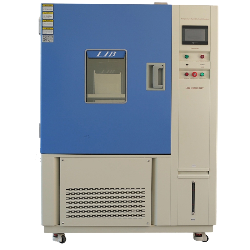
ALT: Condensation Testing for Electronics Building a Reliable Test Cycle
Condensation testing for electronics reproduces the moment when a cold product meets warm, humid air and water forms on its surfaces. The test is designed around the failure that follows: leakage between conductors, corrosion at contacts, insulation loss, display fogging or a reset during operation. A useful cycle controls not only humidity, but also specimen temperature, air movement, dwell time and electrical loading.
A constant 85% relative humidity exposure can miss a failure that occurs in a real warehouse or vehicle. A board may spend the night below the dew point, then enter a warm loading bay. Moisture appears first at connectors and under shields, where it can remain after the chamber air looks normal. Repeated wet-dry transitions add corrosion and residue, so the number of cycles often matters as much as the peak humidity.
A programmable temperature and humidity test chamber can reproduce these transitions with logged profiles.
Condensation begins when the product surface temperature falls below the dew point of the surrounding air. The chamber may report 30°C and 95% RH, but the connector can remain colder because metal and internal mass respond slowly. For that reason, place a small temperature sensor near the critical surface during development runs. It shows when the part, rather than the chamber air, crosses the dew point.
Relative humidity is a ratio that changes with temperature. At a fixed moisture content, warming the air lowers RH; cooling it raises RH. A test profile that jumps from cold to warm without allowing the product to lag may produce little water, while a slower air change can create a heavy film. The profile must match the physical event being simulated.
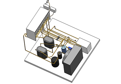
Alt:Refrigeration System
The following workflow gives a laboratory a clear starting point. Adjust limits to the product specification and applicable IEC or customer method, then record every change in the report.
Write down where condensation occurs: a powered outdoor controller, a handheld device taken from a cold truck, or a vehicle module parked overnight. Note the starting temperature, expected humidity, warm-up rate and whether the product is powered. This prevents a generic humidity recipe from replacing the real use case.
Use chamber sensors for control and additional channels for the sample. Attach sensors without blocking vents or sealing surfaces. Record enclosure temperature, connector temperature and, when safe, internal humidity. A difference of only a few degrees can explain why one unit fails while another passes.
Give the product enough time to reach a repeatable thermal state. Large metal housings need longer dwells than small plastic devices. During development, compare a short transition with a slower one and inspect where water forms. The harsher profile is not automatically the more useful profile; it should create the failure mechanism seen in service.
Power cycling can reveal intermittent insulation loss, but it also adds heat that changes condensation. Use current-limited supplies and define the measurement interval. Log resets, communication errors, leakage current and sensor alarms, not only final pass or fail.
Check the item while wet, immediately after the warm dwell and after recovery. Look for droplets under shields, green or dark contact deposits, fogged optics, swollen seals and residue around high-impedance nodes. Photograph the same locations after each cycle. Dry-state inspection alone often misses the short event that caused the reset.
• Surface leakage between fine-pitch conductors when moisture bridges contamination.
• Electrochemical migration under DC bias, producing dendritic growth.
• Contact corrosion at connectors exposed to repeated wet-dry cycling.
• Seal breathing, which draws humid air into an enclosure during cooling.
• Optical fogging that clears after the test but still indicates poor field visibility.
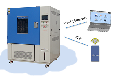
Alt:Condensation Testing for Electronics Building a Reliable Test Cycle
A chamber for condensation work needs stable temperature and humidity control, enough circulation to avoid dead zones, a programmable controller and safe access for powered wiring. LIB chambers can be configured around the product size, cycle range and monitoring points required by the test method. The specification discussion should include heat load from powered samples and the desired recovery after door opening.
A practical setup also considers cleaning and water quality. Mineral residue can turn a marginal insulation design into an artificial failure. Keep the chamber clean, use the water quality required by the equipment and document maintenance with the test record. These small controls protect the value of a long qualification run.
For broader lab planning, review LIB’s climate test solutions and match the cycle to the product environment.
Xi’an LIB Environmental Simulation Industry supplies environmental test chambers for temperature, humidity, corrosion, weathering and ingress-related work. Its engineering approach starts with the sample, test method and operating load, then matches chamber capacity, control range, fixtures and service needs. This helps laboratories obtain usable data rather than simply reaching a nominal humidity number.
A reliable environmental test is built around decisions, not around a chamber display. Before the run, define the failure evidence that will change the design: a first visible crack, a leakage limit, an insulation reading, a reset or a contact resistance shift. During the run, keep the specimen identity, fixture position and sensor channel tied to each observation. After the run, compare the result with a control sample and review any deviation from the approved profile. This workflow makes a borderline result useful instead of forcing an early pass or fail. It also helps purchasing teams compare equipment fairly. A chamber with clear alarms, repeatable recovery and accessible data can reduce retesting even when its headline capacity is similar to another system. For production materials and electronics, that traceability matters because small changes in storage, assembly or surface contamination can change the result. The final report should state the exposure conditions, observations, functional outcome and next action in plain language. That record gives design, quality and supplier teams a common basis for the next decision.
Condensation testing becomes useful when it recreates the product’s thermal lag and the electrical conditions present during wetness. Define the field event, measure the critical surface, control transitions and inspect both wet and recovered states. A well-documented temperature and humidity chamber cycle can expose insulation, connector and enclosure weaknesses early enough to correct them.
It uses controlled temperature and humidity changes to form moisture on or inside electronics and checks for functional, insulation and corrosion failures.
No. Condensation depends on the product surface temperature falling below the surrounding air’s dew point.
Powering can reveal real operating failures, but the load and safety controls must be defined because self-heating changes the moisture pattern.
Log chamber temperature and humidity, sample temperatures, cycle timing, electrical status, alarms and observations at wet and dry checkpoints.




 EN


